How to read piping plan drawing
Table of Contents
Table of Contents
Have you ever been frustrated while trying to read a pipe drawing? Whether you’re a novice or experienced engineer, pipe drawings can be complex and difficult to understand. Don’t worry, in this article, we’ll cover the basics of how to read pipe drawings and provide tips to make the process easier.
Challenges of Reading Pipe Drawings
Reading pipe drawings can be a challenging task due to the complexity of the diagrams and the intricate details that need to be understood. These challenges are further compounded by the different symbols, lines, and shapes used to represent different aspects of the pipe system. Additionally, different industries have their own standards and conventions, which can add to the confusion.
Understanding the Basics of Pipe Drawings
Before diving into the details of reading pipe drawings, it’s crucial to understand the basics. A pipe drawing is a two-dimensional diagram that represents a three-dimensional piping system. These drawings typically follow industry standards, such as ASME or ISO, and consist of symbols and lines that represent various components and connections.
Additionally, there are two types of pipe drawings: orthographic and isometric. Orthographic drawings show the top, front and side views of the pipe system. Isometric drawings display the pipe system at an angle, which helps visualize the system in 3D.
Main Points of How to Read Pipe Drawings
When reading pipe drawings, it’s important to remember the following key points:
- Understand the symbols and lines used to represent different components and connections.
- Identify the type of drawing - orthographic or isometric - to visualize the pipe system correctly.
- Use a scale to determine the pipe sizes and measurements accurately.
- Follow industry standards to ensure compliance and accuracy.
Understanding Piping Isometric Drawings
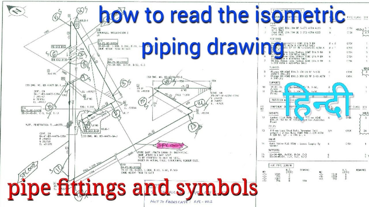
One of the most common types of pipe drawings is isometric drawings. These drawings provide a 3D view of the pipe system and are effective for visualizing and understanding the entire system.
When reading an isometric drawing, it’s essential to know the different symbols and lines used to represent pipes, fittings, and other components. These symbols and lines may differ from industry to industry, so it’s essential to follow the appropriate standards.
Additionally, understanding the different views and projections used in isometric drawings can make the process of reading pipe drawings much more manageable.
Tips for Reading Piping Plan Drawings
Piping plan drawings are used to lay out the system’s pipework, and they are essential for understanding the pipe system’s layout in a building or facility.
One tip for reading piping plan drawings is to use different colors to differentiate between the hot and cold water piping. This technique can help avoid confusion and ensure the accurate installation of the system.
Another tip is to read the drawings carefully and to note any specific details or measurements. This attention to detail can save time, money, and resources down the line.
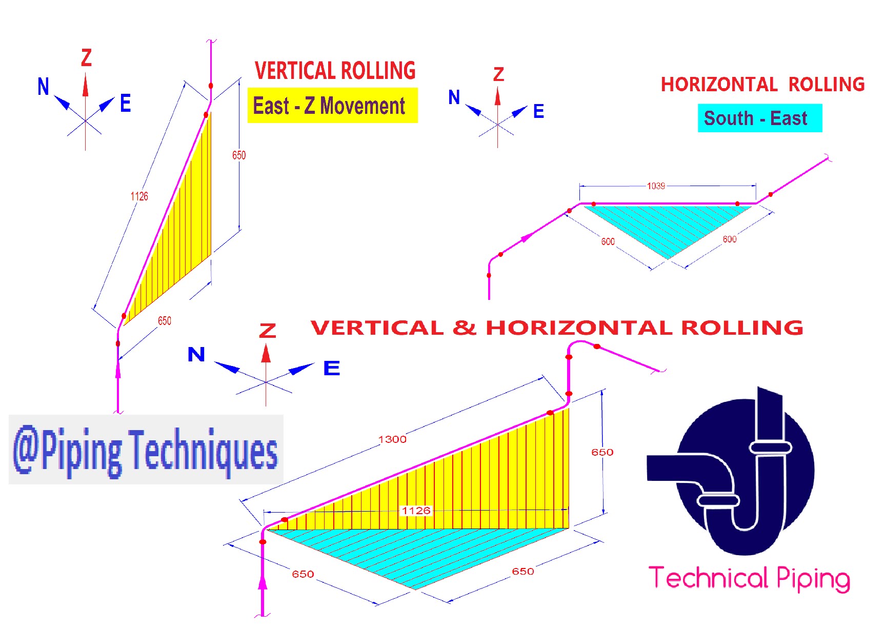
Reading Rolled Piping in Isometric Drawings
When reading piping layouts in isometric drawings, it’s essential to understand the concept of rolling offsets. Rolling offsets allow pipes to be installed at angles, making it easier to navigate around obstacles, such as walls and pillars.
To read rolled piping in isometric drawings, it’s crucial to understand the symbols and lines used to represent these offsets. Additionally, understanding the measurements and angles is essential for accurate installation and compliance with industry standards.
Question and Answer
Q: How do I read the piping size and measurement in pipe drawings?
A: To read the piping size and measurement in pipe drawings, you need to use a scale that is typically provided on the drawing. The scale will help you determine the dimensions accurately, and you can use this information to select the appropriate pipe sizes and fittings for the system.
Q: What are the different types of pipe drawings?
A: The two primary types of pipe drawings are orthographic and isometric drawings. Orthographic drawings display the front, top, and side views of the system, while isometric drawings present a 3D view of the system.
Q: Why are industry standards crucial for reading pipe drawings?
A: Industry standards ensure that the drawings are consistent, accurate, and comply with safety regulations. Following these standards will help avoid errors, confusion and ensure that the system is installed efficiently and safely.
Q: What is the importance of rolled offsets in pipe drawings?
A: Rolled offsets allow pipes to be installed at angles, which makes it easier to navigate around obstacles and maintain the correct flow rate. Properly understanding and reading rolled offsets in isometric drawings can help ensure the correct installation of the system.
Conclusion of How to Read Pipe Drawings
Reading pipe drawings can be challenging, but following the correct techniques and knowing the different symbols and lines used in the drawings can make it much easier. Understanding the different types of pipe drawings and following industry standards will help ensure accurate installation, compliance with regulations, and the proper functioning of the pipe system.
Gallery
Isometric Pipe Drawing At GetDrawings | Free Download

Photo Credit by: bing.com / isometric pipe drawing piping pdf exercises read getdrawings
Isometric Pipe Drawing At GetDrawings | Free Download

Photo Credit by: bing.com / isometric drawing piping pipe plumbing symbols pdf drawings fittings getdrawings exercises vent revit line list diagram paintingvalley sloping
PIPING Isometric Drawings

Photo Credit by: bing.com / pipelines
Piping-How To Read Pipe Rolling/Offset In Isometric Drawing? - Clipzui.com

Photo Credit by: bing.com / isometric offset
HOW TO READ PIPING PLAN DRAWING - YouTube

Photo Credit by: bing.com / piping plan drawing


