How to draw electrical schematics
Table of Contents
Table of Contents
If you’re an electrical engineer or an aspiring one, you know that drawing electrical schematics is a crucial part of the job. But let’s face it, it’s not the easiest task in the world. It requires precision, accuracy, and a lot of patience. In this article, we’ll dive deep into how to draw electrical schematics so you can master this skill and excel in your career.
Have you ever found yourself struggling to draw electrical schematics and not knowing where to start? You’re not alone. Many people face the same challenge when starting. The good news is that once you learn the basics, it becomes easier. One of the biggest pain points is trying to make everything fit into the drawing while keeping it neat and legible.
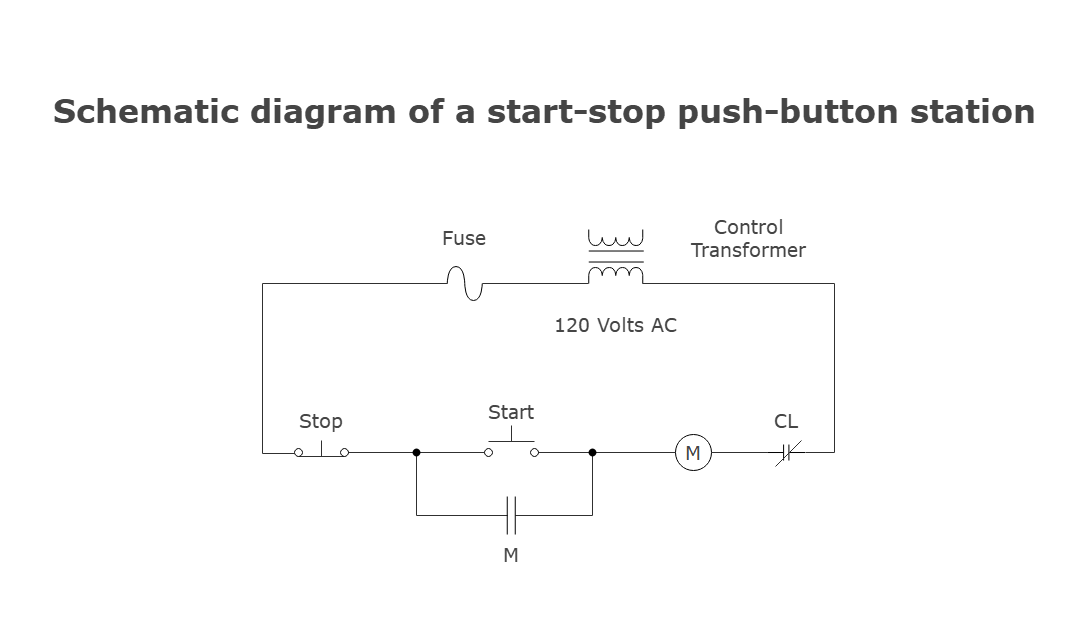
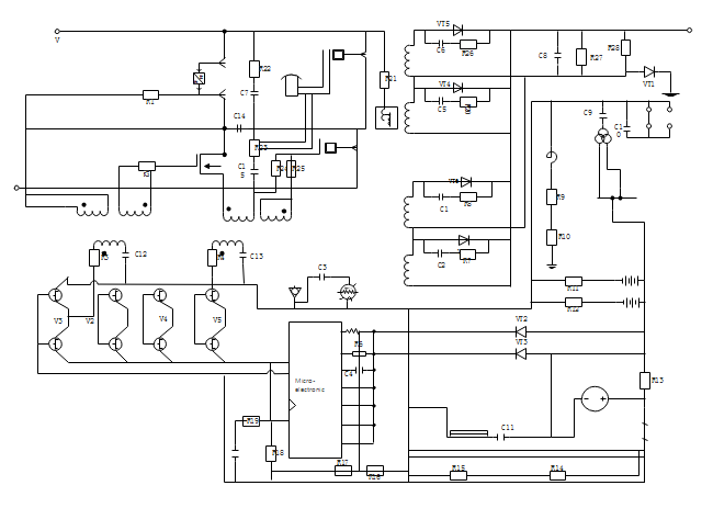
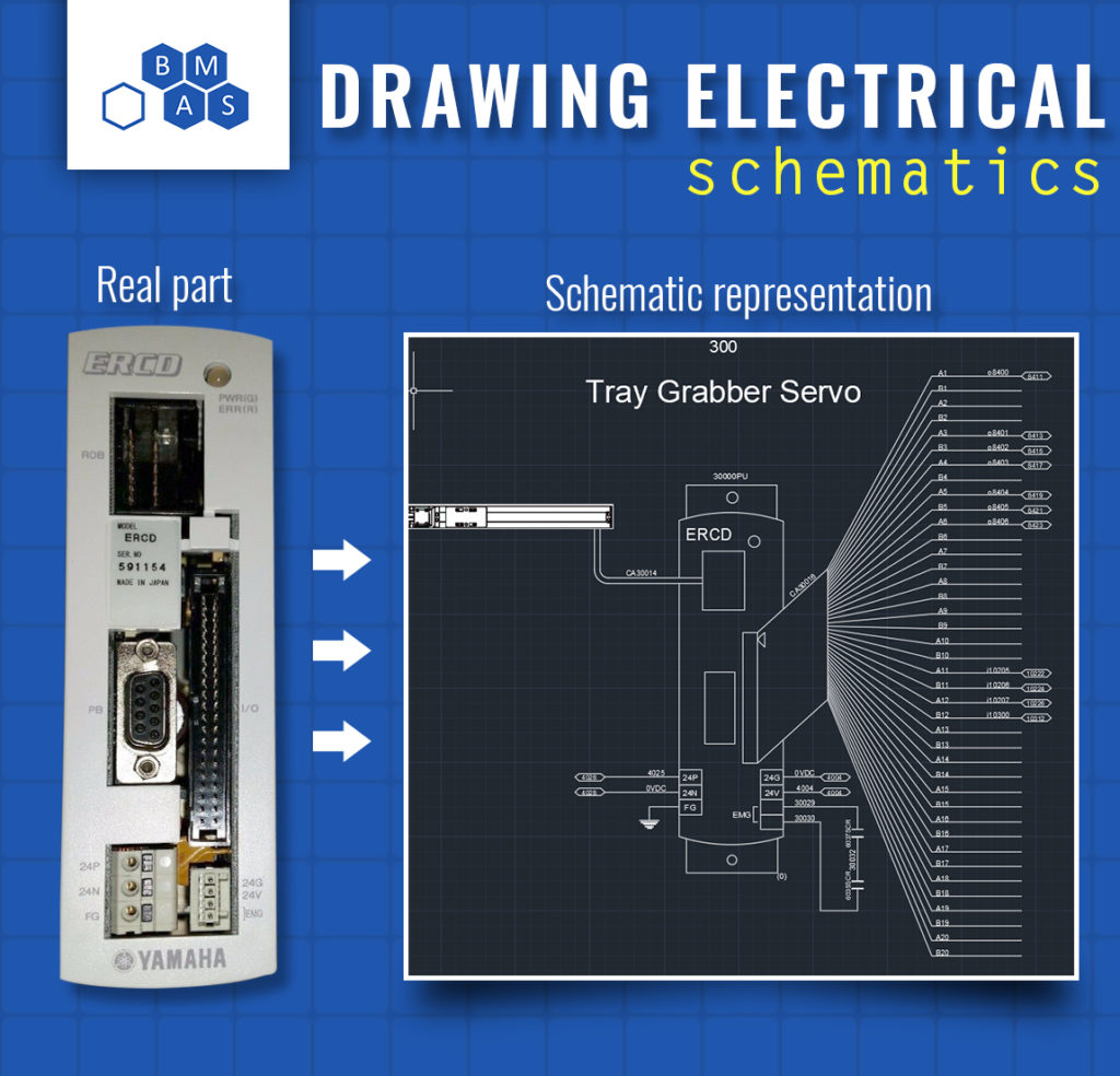
The target of drawing electrical schematics is to create an accurate and comprehensive representation of an electrical circuit. It’s a visual representation of how different electrical components work together to achieve a specific functionality. It’s important to have a clear understanding of electrical symbols, diagrams, and how to represent different types of circuits.
In summary, when it comes to drawing electrical schematics, you need to master the architectural design of the circuitry, understand electrical symbols and their meaning, and have a clear understanding of electrical circuits.
The Steps to Draw Electrical Schematics
One way to approach drawing electrical schematics is to follow a step-by-step guide. Here is a simplified process to get you started:
Step 1: Determine the circuit function and features.
 Step 2: Draw the basic circuit diagram.
 Step 3: Add the electrical symbols.
 Step 4: Add the component values and ratings.
 Step 5: Check for errors.
Tips for Drawing Electrical Schematics
One of the best ways to improve your electrical schematics drawing skills is to learn from hands-on experience. Shadowing an electrical engineer who has many years of experience can help you learn common mistakes to avoid and practical tips to draw neat and efficient circuits. One personal experience that stood out for me was when I was creating a schematic for a new product design. I found myself in a situation where I had to use multiple symbols to represent one component. Upon checking with a colleague, I found out that it was incorrect and that there was a better way to represent it.
To make your electrical schematics drawing easy and efficient, you can follow some best practices:
1. Use grid paper to make your drawings neater and more organized.
2. Use proper electrical symbols to make your diagrams more accurate.
3. Color code your diagrams to make them easier to understand.
4. Clearly label your diagrams to make them more legible and error-free.
Importance of Electrical Schematics
Electrical schematics are essential when it comes to designing any electrical circuits, machines, or products. They provide a systematic perspective of how each electrical component is connected and contribute to the machine’s overall functionality. Additionally, schematics help in identifying problematic connections or short circuits, which can be fatal if not fixed.
Software for Drawing Electrical Schematics
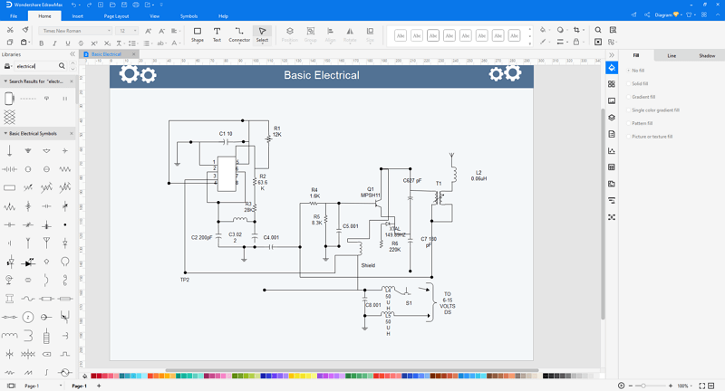
With the advent of technology, many software tools can help make electrical schematics drawing faster and more efficient. Some popular software tools for drawing electrical schematics include:
1. Edraw
2. Autodesk Eagle
3. SmartDraw
4. SchemeIt
Conclusion
Drawing electrical schematics may seem complex, but it’s a learnable skill that you can acquire with some effort and dedication. By following best practices, learning from personal experiences and mentors in the field, and using the right tools, you can master this skill and excel in your career. With the increasing use of software tools, it’s becoming easier to create schematics today, but it’s important to have a clear understanding of the concepts behind them.
Question and Answer
Q1. Why is drawing electrical schematics important?
A1. Electrical schematics are essential when it comes to designing any electrical circuits, machines, or products. They provide a systematic perspective of how each electrical component is connected and contribute to the machine’s overall functionality.
Q2. What are some common mistakes to avoid when drawing electrical schematics?
A2. Common mistakes to avoid include using incorrect symbols or incorrect labeling of components, not following standard practices, and not thoroughly checking to make sure there are no errors.
Q3. How do you represent complex circuits in an electrical schematic?
A3. You can represent complex circuits using multiple symbols to represent one component or by creating separate diagrams for different functionalities and combining them in the end.
Q4. What software tools can I use to draw electrical schematics?
A4. Some popular software tools for drawing electrical schematics include Edraw, Autodesk Eagle, SmartDraw, and SchemeIt.
Gallery
Electrical Drawing At GetDrawings | Free Download

Photo Credit by: bing.com / electrical drawing getdrawings read wiring
Step To Step Guide - How To Draw Electrical Schematics

Photo Credit by: bing.com / schematics electrical draw electronic schematic step guide own
How To Draw Electrical Schematics - Edraw

Photo Credit by: bing.com / electrical draw schematics diagram schematic edrawmax example
How To Draw Electrical Schematics - Edraw

Photo Credit by: bing.com / electrical draw schematics notes schematic
PLCs Are Not Toilets: Learning To Draw Electrical Schematics - Breen

Photo Credit by: bing.com / draw breen toilets plcs


